 English
 Česká republika
 Germany
 France
 España
 Italia
 Sverige
 Polski
 Nederland
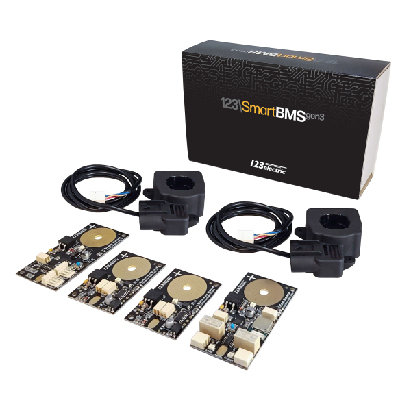
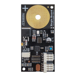
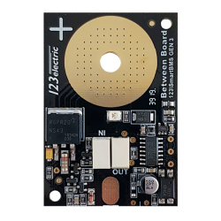
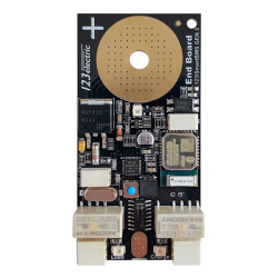
123electric 123ELECTRIC BMS123 Smart Gen3 - Complete Set (4 Cells) With Bluetooth 4.0
Manufacturer:
123electric

To order
This article is discontinued. Please, chose another one!!!
GWL/Power BMS123 Smart Gen 3 – a complete solution for LFP, LTO, NMC and Li-Ion cells to make battery with Bluetooth monitoring and management using your smart phone, iPad, tablet or other device.


