English
 Česká republika
 Germany
 France
 España
 Italia
 Sverige
 Polski
 Nederland
Previous
Next
Blog - Tests and diagnosis
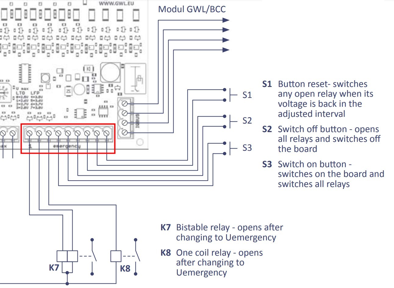
Details of the Emergency Output for CPM1
Pin # 1 - Main Turn-on Impulse - 150 ms pulse to GND
The pin will be connected to GND for 150 ms when the board is powered on, or after the board has been reset (and restarted).
This pin is designed to give an impulse to the bistable relay or to give a power-on impulse to the auxiliary controls (circuits) to set the system in “regular operation”
Pin # 2 - Emergency Voltage Level Reached Impulse - 150 ms pulse to GND, with a delay of 30 seconds
U Emergency condition is reached this way: Low voltage – the voltage of any cell reached bellow [U min less 0.3V] and stays in this condition for at least 30 seconds. High Voltage – the voltage of any cell reached above [U max plus 0.3V] and stays in this condition for at least 30 seconds.
The pin will be connected to GND for 150 ms when the U Emergency condition is reached.
This pin is designed to give an impulse to the bistable relay or to give a power-on impulse to the auxiliary controls (circuits) to issue the ultimate warning about the U Emergency situation of the battery pack.
Pin # 3 - Emergency voltage indication – NC (normally closed to GND)
Under the normal operation condition this pin is “normally closed” to GND. If the Emergency Voltage Level is reached (see above the explanation) this output will disconnect from GND and will become potential-less.
Is output is designed for a standard single-coil relay or for a connection to the auxiliary controls (circuits).
Pin # 4 + # 5 Main Remote Power ON control – START (> 2 sec)
If the board is powered-off (after the Shutdown), the connection of the pins #4 and #5 for two seconds will wake up the board and the board will power on.
The connection to of the pins #4 and #5 for 2 seconds is identical to pressing the “START” button for 2 seconds.
The pins #4 #5 allow for the remote power-on of the CPM1 board.
Note: if the pins #4 #5 are permanently connected together, the board will keep working and it will not respond to the “Power-off” and “Reset” signals.
Pin # 6 + # 7 Main Remote Power OFF control – SHUTDOWN (> 1 sec)
If the board is running, or in case the board has become unstable, the connection of the pins #6 and #7 for one second will shut the board down. All signal outputs will be reset to default - disconnected from GND).
The pins #6 #7 allow for the remote shutdown of the CPM1 board.
Pin # 8 + # 9 Main Remote RESET control (> 1 sec)
If the board is running, or in case the board has become unstable, the connection of the pins #8 and #9 for one second will RESET the board. All signal outputs will be reset to default - disconnected from GND, and the board will resume the operation.