Blog - Installation diagrams
The CSOD Project - design and ideas
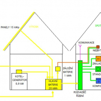
The GWL/Team has spent countless hours on the discussions, projections and modifications of the initial design of theCzech Sustainable House (CSOD)project.
As promised, we will be releasing majority of the CSOD documentation so that all customers and supporters can see what the GWL/Team ha
DC Wire Color Coding Standards
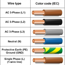
The table shows the color coding for AC wires in the installations.
DC Plus Pole (+) – Red DC Minus Pole (-) non-grounded – Blue (#1) DC Minus Pole (-) grounded – Black (#2) Protective Earth (PE) or Ground (GND) – Yellow/Green
Notes:
#1 For majority DC systems the battery poles and all DC wires must be
AC Wire Color Coding Standards
The table shows thecolor coding for AC wiresin the installations - IEC 60446.
AC 3-phase Live (L1) – Brown AC 3-phase Live (L2) – Black AC 3-phase Live (L3) – Gray Neutral (N) – Blue Protective Earth (PE) or Ground (GND) – Yellow/Green AC Single Phase Live &ndash
GWL/Modular - BMS Basic
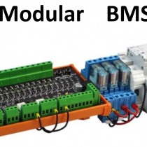
The primary setup of the GWL/Modular components as BMS-Basic.
The BMS Basic provides the “basic” or primary protection of the battery pack up to 16 cells. The management of the battery pack is handle by the CPM1 board.
Integration of the GWL/Modular with Victron Energy products
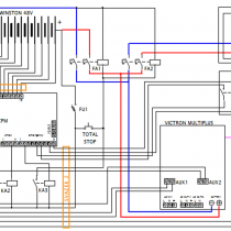
The reference of theshows the possibility of the integration of the GWL/Modular components with theVictron Energy products.
In this installation the CPM1 communicates (by means of auxiliary relays) with theAUX1 and AUX2 of Victron Multiplus, and the
GWL/Modular – CPM1 - Auxiliary Relays for High Power...
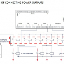
As seen from the demonstration designs provided by GWL and also from the manual of the, the high-power outputs need to be connected by means of the auxiliary relays.
The auxiliary relaysprovide another layer of protection and disconnectionbetween the battery pack e
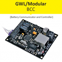
GWL/Modular BCC - see the web
is an expansion, independent communication extension board designed to be used exclusively. This board expands the battery protection functions and enables remote management of batteries protected by the CPM.
Check the printscreens of the web interface. You can stu
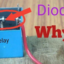
The relay with a flash back diode. Observe the polarity!
Some time ago, GWL/Team has explainedto be connected in parallel to the relay coils when switching relays by transistors.
Recently there were few cases when customers installed a professionally made relay that alrea
A complete solution from the GWL/Team
This is the work of the GWL/Team. As a part of, the GWL/Team members create a customized solution to help the customer according to his needs.
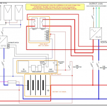
In this design schematics, a customer is looking for a solution of an off-grid cottage.
Components used: 4x PV solar panels 165Wp, MPP
GWL/Modular Flexi Pack
The GWL/Team is busy working on the first pre-production batch for the. The initial delivery should be ready during 8/2020 and the promotion on the web site is scheduled for 9/2020.
Perhaps you ask what takes so long. For example just finding a reliable mechanical-design compo

 English
 Česká republika
 Germany
 France
 España
 Italia
 Sverige
 Polski
 Nederland