 English
 Česká republika
 Germany
 France
 España
 Italia
 Sverige
 Polski
 Nederland
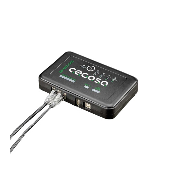
CEGASA TCCv2.0 BTH SYSTEM
Contact us:
phone: +420 277 007 550
email: [email protected]
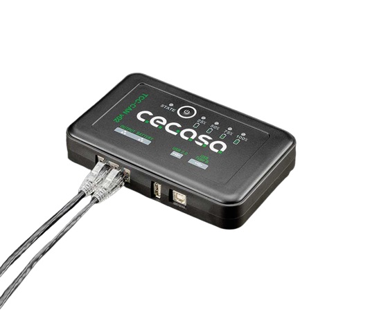
The main purpose of the TCCv2.0 is to be able to use a CEGASA battery system (ULTRA175) with commercial inverter/charger equipment or other equipment or applications that may have CAN BUS communications.
For such purposes, the TCCv2.0 communicates, on the one hand, with the system’s batteries and, on the other, transmits information from these to the application’s end equipment via CAN BUS communications. In the case of the ULTRA175 the maximum number of batteries that can be connected in the system is 4. The TCCv2.0 system uses CAN BUS communications to read the present state of the batteries connected on the serial bus.
Some of the most important registers read are voltage, current, state of charge (SOC), temperatures, alarms... Once it has the information about the battery, the TCCv2.0 system transfers this to the end equipment using CAN BUS communications. The CAN registers that are sent to the end equipment refer to the current state of the battery system (voltage, current, temperature, SOC...), it also includes the State of Function (SOF): constantly sending the optimal voltage and current data needed to carry out an optimal charge/discharge process of the battery system based on the SOC and battery temperatures.
- TCCV2.0 Battery Cable connected between the battery and the TCCV2.0 system; (RJ45 CAT5e PARALLEL TYPE) 1.5 metre long, connected between the TCCV2.0 system and the HUB (output) or the ULTRA module.
- Communications terminating resistor on RJ45 connector;this is connected to the TCCv2.0 housing called OUTPUT
- USB drive with SW, required to configure. the TCC CAN (compatible inverter brand, battery model, total number of batteries in installation, etc.); Manuals included.
Use a standard direct/parallel ETHERNET cable of the required length for the installation (**) If using CERBO GX and VENUS GX systems, it is advisable to connect the cable mentioned in the previous point to the port called BMS-CAN.
SMA and Studer Inverters
Use a standard direct/parallel ETHERNET cable of the required length for the installation
Ingeteam Inverters
If using Ingeteam inverters, the installer has to prepare a custom cable, since the connection to these inverters is made using quick connectors. The three available CAN wires (CAN-H, CAN-L and GND) should be connected as follows:
- Pin 2: GND
- Pin 4: CANH
- Pin 5: CANL
Solis & Goodwe Inverters
Two options a) The installer can prepare a direct/parallel ETHERNET cable, pinning out only pins 2, 4 and 5
Read the full user manual here: OPEN MANUAL


