123ELECTRIC BMS123 Smart Gen3 - Complete Set (4 Cells) With Bluetooth 4.0

Manufacturer: 123electric
Art.#: BMS123SM-G3-SET
284.90$Price without VAT:
Stock status : 1 pcs


Individual pricing for large scale projects and wholesale demands is available.
Contact us:
phone: +420 277 007 550
email: [email protected]


Shipping weight: 0.47 kg
GWL/Power BMS123 Smart Gen 3 – a complete solution for LFP, LTO, NMC and Li-Ion cells to make battery with Bluetooth monitoring and management using your smart phone, iPad, tablet or other device.


BMS123 Smart Gen3


  • LTO compatible, operates on cell voltages between 1.5V and 5.0V
  • High accuracy SOC, dual range current sensors to measure a wide range of currents up to 50
  • Error history to see when, what cell and which error occurred
  • SOC logging of the last week.
  • More accurate temperature measurement near cell pole
  • Over the air firmware update
  • Easier configuration
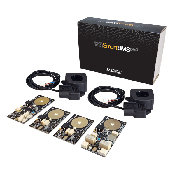
Complete set package (4 cells) you will receive:
  • 1 pc. of cell Begin module
  • 1 pc. of cell End module
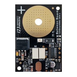
  • 2 pc. of cell Between modules
  • Cell modules interconnection wire
  • Two current sensors 500A to monitor Ingoing and Outgoing current independently

Check the BMS123 Smart product line.

Demonstration video of BMS123 Smart Gen3 assembly

Simple installation, easy settings, smart operation and maximum protection!

BMS123 Smart is a fully modular system. Each cell of the battery equipped with one small size circuit-board. There are three types of cell circuit-boards needed for the installation. One Begin board installed on the first cell, One End board installed on the last cell and a regular cell board on each cell between the first and the last cell.

For a battery pack made of 4 cells (12V) you need only one Begin, one End module and two regular cell modules.


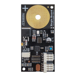
Photo of the Cell Begin module

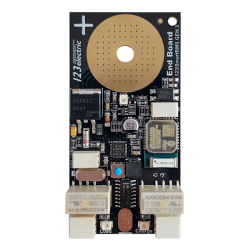
Photo of the Cell End module

For a larger size battery packs (24V, 48V, etc) you just start with the Complete Set (of 4 cells) and you simply purchase additional number of the regular cell modules to install on additional cells in between the first and the last cell. It is easy to make a complete system for any number of cells!


Example of the configuration of the battery packs:

  • 24V pack (with 8 pcs LiFePO4 cells): BMS123 Smart - Complete Set has 4 cells (1x First IN, 1x Last OUT, 2x Single CM) for additional 4 cells just buy 4 more Single Cell Modules (CM).
  • 48V pack (with 16 pcs LiFePO4 cells): ): BMS123 Smart - Complete Set has 4 cells (1x First IN, 1x Last OUT, 2x Single CM) for additional 12 cells just buy 12 more Single Cell Modules (CM).

Example of the configuration 2P4S (ex. 12V (2x100Ah)) battery packs:

For this installation you need again only 12V BMS set. Two cells in parallel are still just one cell.


BMS123 Smart Application


ev-charging

Simple instillation right at the cell level

BMS123 Smart is really Smart: There is no Main Controller Unit for this BMS system! Everything is integrated at the cell modules directly. The IN and OUR cell modules contain all the hardware components for the basic operation of the whole BMS system. Additionally the OUT cell module gathers all relevant data and transmits them via Bluetooth 4.0 LE (low consumption) to your iOS or Android Tablet of Phone.

The Access to information about your battery pack was never easier. Monitor everything remotely, including daily PV production, daily energy consumption, or for example voltage of all cells at the single screen. Have complete overview of your home energy storage at you Smartphone or tablet!

Smart advantages of the BMS123

  • Small size board installed directly at the terminals of each cell
  • Single wire communication. Easy to assemble the battery pack
  • Simple wiring design of the whole system designed for energy storage markets
  • No additional Main Controller unit
  • No external battery is needed for operation; the BMS is powered directly from the battery pack
  • Detailed monitoring and balancing function for each cell independently
  • Check the status of all cells at single screen
  • Excellent pricing ratio: robust and reliable system at very competitive price
  • Adjustable integrated bi-stable low power relays allowing you to disconnect charger and load at predefined levels
  • Optional Free iOS or Android based software to get the extended monitoring dash-board


ev-charging

BMS123 Smart and Victron


Demonstration video of BMS123 Smart and Victron devices


Besides connecting one of the Victron Energy Lithium battery systems to a Multi or Quattro, it is also possible to connect a system from another manufacturer. In most installations, the Battery Management Systems (BMS) that comes with a type of lithium battery systems will need to have control over the charging and discharging of the battery. In general they will want to stop the charging process when the maximum cell voltage increases above a threshold, and also they will want to switch off loads that are discharging the battery when the minimum cell voltage drops below its threshold

Check the connection of the with The Victron inverters: These are equipped with AUX I/O (allow to charge) and Temp sense (allow to discharger ports. The charge/discharge contact functionality is available only in case the Lithium assistant function is activated.

BMS123 connection diagram


BMS123 Smart Relay


BMS123 connection diagram

The innovative solution for the BMS123 Smart high current loads. BMS123SM-REL is the product code for the BMS123 Smart - Dual Latching Relay block .

This relay blocks allows to control two latching (bistable) DC relays. You can connect the DC load to the BMS123 Smart in an easy way.

The OUT-board of the BMS123 Smart has two small relays. These relays are not designed for high current loads. However, now you can connect the BMS123SM-REL to the OUT board and control the high current load.

The main advantage: if you connect the standard DC contactor, it always need the power to keep the contacts tightly closed. This means the DC contactor always drains some every for its operation. The advantage of the BMS123 Smart Relay is that it is using the latching relays. The latching relay will not consume any energy after it turns the contact ON or OFF.

Please note that the BMS123 Smart Relay is designed only for 12V to 48V DC applications. The maximum loading for one relay is:

  • 12V - max 120A DC (100A and less recommended for continuous use)
  • 24V - max 120A DC (80A and less rec. for con. use)
  • 48V - max 60A DC (40A and less rec. for con. use)

Example schematics with BMS123 Smart with Relay

BMS123 connection diagram

Recommended connection of BMS123 Smart with charger and load

BMS123 connection diagram

    Example
    An application has a nominal voltage of 24V, the total load is 200A. Connected are a two inverters, both 100A. One inverter is used for the sockets,
    water kettle and lightning, the other inverter for the water heater (2000W).


BMS123 Smart Extended Module


BMS123 connection diagram
Extended Module is supplied with both Molex connectors and cables.

The module adds the following functionality to the BMS123 Smart system:

  • 4 configurable relays - switch relay on at time or conditions
  • 2 individual CAN bus connections
  • Control Elcon/TC Charger via CAN bus interface
  • Broadcast BMS settings on CAN bus
  • Compatible with EV charging stations using the J1772/IEC 62196 protocol - adaptive charging. Extended module limits charging current to the maximum current of the charging station/vehicle.
  • Control two analog gauges to indicate fuel level (state of charge) and current consumption
  • Isolation detection - measure the isolation resistance between the power supply and an isolated battery pack

EV Charging
Electric vehicles can be charged at charging stations using the J1772 protocol. The Extended Module communicates with the charging station and gets the maximum allowed current. This advertised current will be used.

Isolation detection function
Battery packs using high voltage need to be isolated from the electronic power supply like a 12V battery. It is important to continuously measure this isolation resistance between the high voltage pack which the BMS manages and the power supply of this Extended Module. This can be done with the isolation detection.

PC connection
Extended moduel is euipped by the USB port for PC based devices connection not only in the vehicle.
The software for the Extended Module consists of different functions:

Monitoring
The most important data like total pack voltage, state of charge and individual cell voltages are shown.

BMS data
Global BMS settings like minimum cell voltage, maximum cell voltage and temperatures have to be configured. Also all BMS data can be send on the CAN bus.
NOTE: the BMS does NOT use the minimum voltage, maximum voltage, minimum temperature and maximum temperature configured by the Bluetooth module.

CAN BUS messages
It is possible to send the most important BMS data like voltages, temperatures, settings and status on a CAN bus. Choose the the desired CAN bus network (1 or 2) and fill in the start message ID. The BMS will send a 8 different CAN bus messages. The first one on the start address (N), second one N+1 etc.
See the attached manual for more information.
ev-charging

Configurable relays
Four relays can be independently configured on day of week, hysteresis or boolean logic. There is also an “invert output” option of the relay


Weight (kg) 0.34
icon 123ELECTRIC BMS123 Smart Gen3 - Complete Set (4 Cells) With Bluetooth 4.0 GWL/Power BMS123 Smart Gen 3 – a complete solution for LFP, LTO, NMC and... 284.90$
26 visitors online.
All Rights reserved © 2024 GWL Group a.s. - GShop v. 1.4.8