English
 Česká republika
 Germany
 France
 España
 Italia
 Sverige
 Polski
 Nederland
Previous
Next
Blog - BMS Systems
How to manage chargers by BMS123 Smart Extended module
You can use the BMS123 Smart with Extended Module to control of charging by Chargers for LFP/LTO with BMS input (POWxxVxxA-D1).
Following example shows how to reduce charging current in case the one LiFePO4 cell excede 3.6V and stop the charging in case the one LiFePO4 cell excede 3.65V. The charging starts again at higest current in case the cell will have lower voltage then 3.5V. The cell is one of all in the battery pack with highest voltage level.
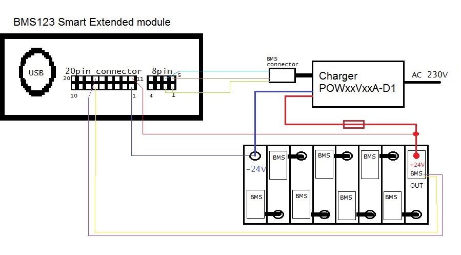
Connection Diagram:
The LFP/LTO Chargers D1 are supply with BMS connection cable. The blue wire is connected to the PIN6, brown wire to the PIN5 and green wire to the PIN1 and PIN2 of the 8PIN connector in Extended module.
Other connections are described in the manual and software discription.
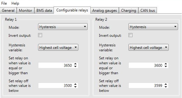
Open the software of Extended module and switch to the Configurable relays page.
Switch Relay 1 and Relay 2 to the Hysteresis Mode with the Highest cell voltage variable.
Relay 1 manages ON/OFF signal wires of the Charger and Relay 2 manages LOW/HIGH current signal wires of the Charger.
The voltage values must be in mV (3.65V= 3650mV).
Relay setting
This setting is example only which follow the battery pack setting in this case. You can use your own setting of course.