English
 Česká republika
 Germany
 France
 España
 Italia
 Sverige
 Polski
 Nederland
Previous
Next
Blog - Battery Monitoring
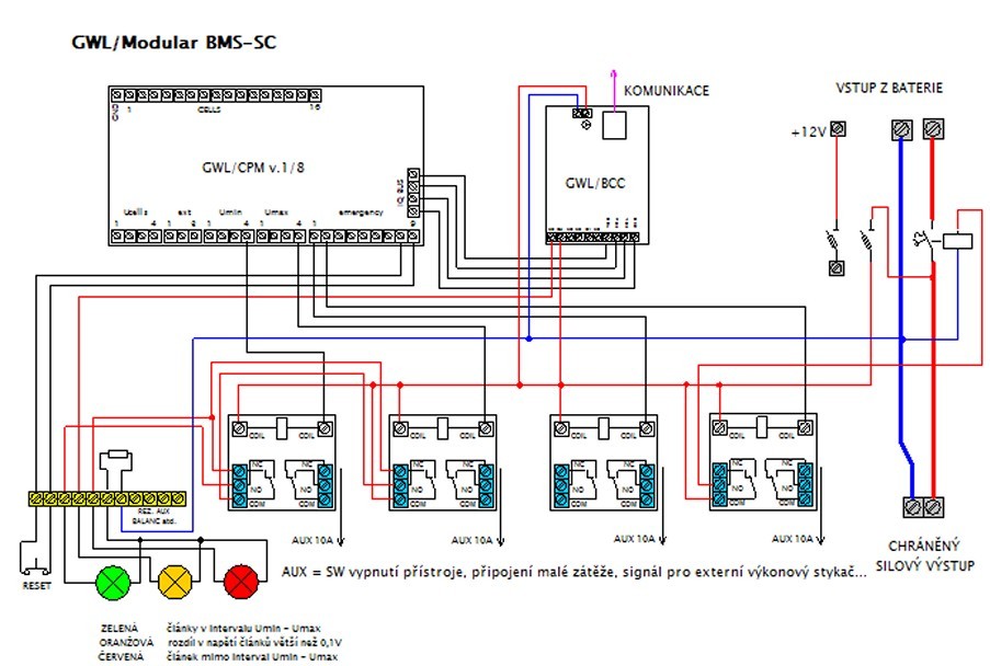
GWL/Modular - BMS SC Setup
The basic wiring diagram for the BMS SC setup. In this setup, there is the BCC communication module added to the CPM1. There are four auxiliary relays that respond to Umin, Umax, Uemergency and the controlling signal from BCC. There is also a 3-LED status for the condition of the setup.
More details can be requested as the paid support by the GWL/Team.